CPU & Hardware low level interactions...in x-86...
CPU can easily add, subtract, multiply & divide! How does it talk to devices?
We all have used simple CPU instructions to read from memory, write to it or control it in some other way. There are three kinds of buses for this, address bus, data bus and the control bus needs to access memory in access to perform its tasks. Let's suppose you want to read from a memory location @ 0x008C into a register ax in an X-86, you would write something like this: MOV 0x008C, ax and to store some data at the same location this could be used: MOV 0x008C, ax

;; X-86 assembly

; load the register with the value stored @0x008C in RAM
mov ax,0x008C

; store the register value into the memory location
mov 0x008C, ax
If in case we need to load the address into a register we use lea instruction which 'loads effective address' into a register.
All this is used to interact with RAM, what about hardware devices that are connected over through a parallel port or to some GPIO pins. For that, there are 2 ways to access these devices from the assembly,
- IO-Mapped: Use
inbandoutbinstructions to write to a particular IO port. - Memory-Mapped: Map these ports to the virtual memory and use the same
movinstruction to read and write

The CPU needs to talk to either memory or the I/O device, never both. To distinguish between the two, one of the control lines called M/#IO asserts whether the CPU wants to talk to memory (line=high) or an I/O device (line=low).
IO-Mapped IO
The 80386 processor provides a separate I/O address space, distinct from physical memory, that can be used to address the input/output ports that are used for external 16 devices.
The instructions IN and OUT move data between a register and a port in the I/O address space. The instructions INS and OUTS move strings of data between the memory address space and ports in the I/O address space.
According to this link, IN transfers a data byte or data word from the ports which are numbered by the second operand into the register (AL, AX, or EAX) specified by the first operand. Access any port from 0 to 65535 by placing the port number in the DX register and using an IN instruction with DX as the second parameter. These I/O instructions can be shortened by using an 8-bit port I/O in the instruction. The upper eight bits of the port address will be 0 when 8-bit port I/O is used.
In assembly: IN AL, 19H receives 8-bits from the port 19H
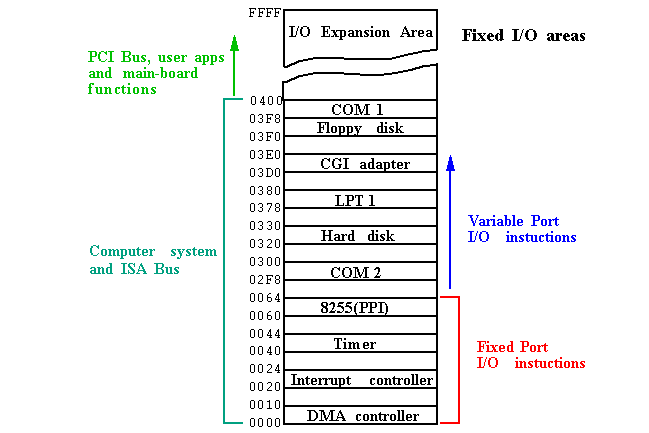
IO-Map
This is a map of hardware mapped to a particular port or a group of ports.

An Example: Blinking a LED (Linux Module)
Connect a light-emitting diode (LED) with a 330-ohm resistor in series across pin 3 (Tx) & pin 5 (Gnd) of the DB9 connector of your PC.
Compile the module and load the serial.ko file into the running kernel using insmod
#include <linux/module.h>
#include <linux/version.h>
#include <linux/types.h>
#include <linux/delay.h>
#include <asm/io.h>

#include <linux/serial_reg.h>

#define SERIAL_PORT_BASE 0x3F8

int __init init_module()
{
    int i;
    u8 data;

    data = inb(SERIAL_PORT_BASE + UART_LCR);
    for (i = 0; i < 5; i++)
    {
        /* Pulling the Tx line low */
        data |= UART_LCR_SBC;
        outb(data, SERIAL_PORT_BASE + UART_LCR);
        msleep(500);
        /* Defaulting the Tx line high */
        data &= ~UART_LCR_SBC;
        outb(data, SERIAL_PORT_BASE + UART_LCR);
        msleep(500);
    }
    return 0;
}

void __exit cleanup_module()
{
}

MODULE_LICENSE("GPL");
MODULE_AUTHOR("Anil Kumar Pugalia <email@sarika-pugs.com>");
MODULE_DESCRIPTION("Blinking LED Hack");
Memory-Mapped IO
Part of the RAM is assigned to hardware registers, writing to such memory location is akin to writing to a device register. Devices also update the memory location and raise an interrupt to let the CPU know that the data is ready to be read.
According to Wikipedia, The hardware of the system is arranged so that devices on the address bus will only respond to particular addresses which are intended for them, while all other addresses are ignored. This is the job of the address decoding circuitry, and that establishes the memory map of the system. As a result, the system's memory map may look like the table below. This memory map contains gaps, which is also quite common in actual system architectures.

One merit of memory-mapped I/O is that, by discarding the extra complexity that port I/O brings, a CPU requires less internal logic and is thus cheaper, faster, easier to build, consumes less power, and can be physically smaller. Regular memory instructions are used to address devices, all of the CPU's addressing modes are available for the I/O as well as the memory, and instructions that perform an `ALU` operation directly on a memory operand (loading an operand from a memory location, storing the result to a memory location, or both) can be used with I/O device registers as well.
In contrast, port-mapped I/O instructions are often very limited, often providing only for simple load-and-store operations between CPU registers and I/O ports, so that, for example, to add a constant to a port-mapped device register would require three instructions:
- Read the port to a CPU register
- Add the constant to the CPU register and
- Write the result back to the port.
Traditionally, serial and printer ports, as well as keyboard, mouse, temperature sensors, and so forth were I/O devices. Disks were sort of in-between; data transfers would be initiated by I/O commands but the disk controller would usually direct-deposit its data in system memory.
In modern operating systems like Windows or Linux, access to I/O ports is hidden away from "normal" user programs, and there are layers of software, privileged instructions, and drivers to deal with the hardware. So in this century, most programmers don't deal with those instructions.
Nowadays, almost everything on an X-86 processor is moving towards memory-mapped IO. Since, we are catering towards our curiosity, knowing how it works may help us sleep well at night.